Joist hanger 2.0 mm One piece
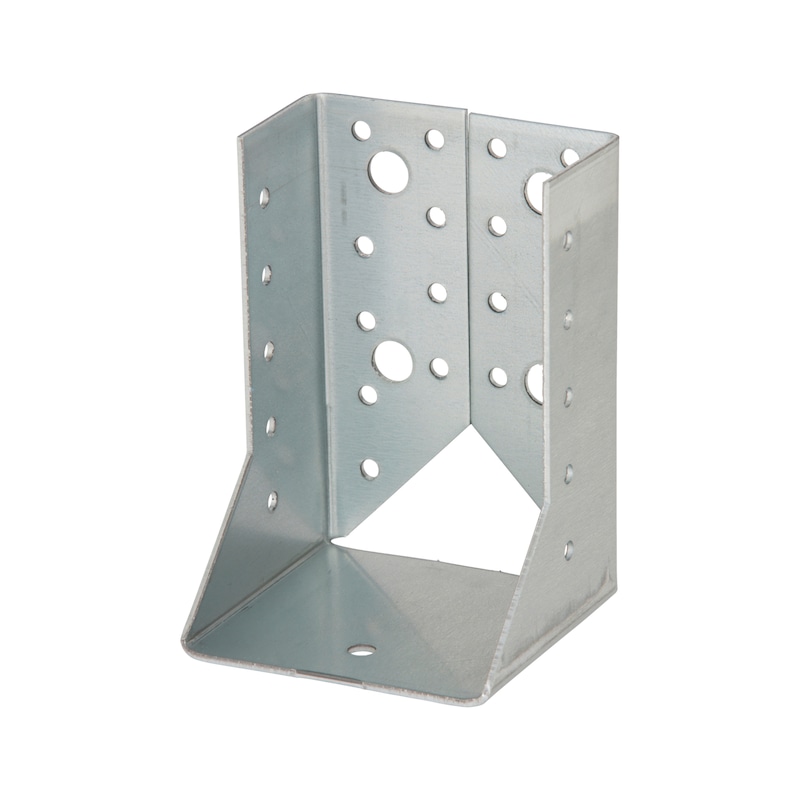
Joist hanger one-part, angled inwards
JOISTHNG-(INTCRANKED)-100X140X2,0

Register now and access more than 125,000 products
- Beams under uniaxial load can be connected to posts of the same width
- Wings angled inwards
- Sheet metal hot-dip zinc-plated on both sides (S250GD +Z275), approx. 20 µm of thickness 2.0 mm in accordance with EN 10367:2004
- Application in utilisation class 1 and 2 in line with EN 1995:2013
European Technical Approval ETA–09/0021
Nail edge clearances in the post must be observed in line with EC5 when designing connections with biaxial loads!
The diameter of bolts/screws may only be max. 2 mm smaller than the diameter of the hole.
The respective basic conditions of the applicable anchor approval must be observed.
Available work documents:
Load tables and detailed processing instructions can be found on the service page www.wuerth.de/holzverbinder.
European Technical Approval ETA–09/0021
Subject to technical changes!
Datasheets(X)
Load-bearing connections of timber joists to wood, concrete or steel in visible areas
Suitable fasteners:
- Ribbed nail in line with EN 14592: 4.0 x 40 to 100 mm.
- ASSY 3.0 Combi in line with ETA 11/0190: d = 10, 12 mm.
- Bolts according to manufacturers' specifications: d = 10, 12 mm.
- Recommended dowels for anchoring in concrete: W-BS; W-FAZ; W-VIZ; WIT-VM 250; WIT-UH 300
 | |
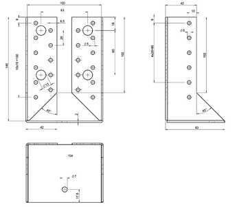
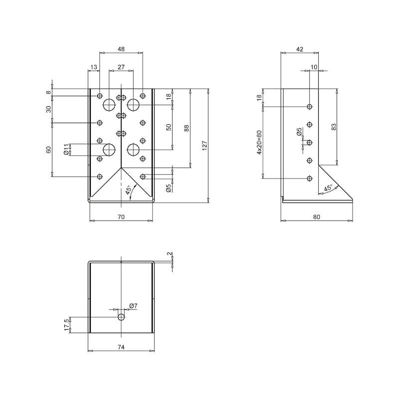
Width x height | 100 x 140 mm |
Thickness | 2 mm |
Number of D 5 mm holes in subcarrier nJ + main carrier nH | 12 + 22 PCS |
Number of D 13 mm holes in subcarrier nJ/main carrier nH | 0 + 4 PCS |
Weight | 416 g |
Depth of underside | 80 mm |
Material | Steel |
Surface | Hot dip galvanized |
Width of wing on nut | 34 mm |
Approval | ETA-09/0021 |
Material designation | S250GD |
Material standard | DIN EN 10326:2004 |
Number of pieces | 1 PCS |
Depth of upper side | 42 mm |
| Partial and complete nailing of Würth joist hanger 2.0 mm with internal wings | |||||||||||||||
| Characteristic load-bearing capacities of Würth joist hangers 2.0 mm; internal wings with Würth comb/anchor nails | |||||||||||||||
| Art. no. | Format in mm | Complete nailing | Partial nailing | ||||||||||||
| Fz,down,Rk | Fz,up,Rk | Fy,Rk | Fz,down,Rk | Fz,up,Rk | Fy,Rk | ||||||||||
| 4x40 | 4x60 | 4x40 | 4x60 | 4x40 | 4x60 | 4x40 | 4x60 | 4x40 | 4x60 | 4x40 | 4x60 | ||||
| 0681 089 120 | 80/120 | 16,0 | 24,5 | 9,4 | 15,2 | 6,2 | 9,5 | 7,8 | 12,1 | 6,7 | 10,6 | 3,7 | 5,7 | ||
| 0681 109 140 | 100/140 | 21,0 | 30,1 | 13,5 | 21.49 | 7,6 | 11,7 | 11,7 | 17,2 | 7,7 | 12,2 | 3,9 | 6,1 | ||
| 0681 110 160 | 120/160 | 27,3 | 38,7 | 19,5 | 30,5 | 10,0 | 15,3 | 13,4 | 20,1 | 12,5 | 17,2 | 5,2 | 8,0 | ||
| 0681 110 180 | 140/180 | 33,1 | 42,9 | 25,0 | 38,5 | 11,4 | 17,5 | 17,9 | 25,8 | 13,7 | 21,0 | 6,3 | 9,7 | ||
Select RAL-colour code
!! NOTE: On-screen visualisation of the colour differs from real colour shade!!


